In the CAM processing of a workpiece, it's common to encounter surfaces that are steep in some areas and flat in others. This irregularity often makes it impossible to complete the entire machining process in one go. However, in many cases, ensuring the surface finish requires all faces to be processed in a single operation. Is there an alternative approach that can combine these two methods into a more efficient and effective machining process?
In 3D CAD/CAM software, the angle-restricted finishing feature provides a powerful solution to this challenge. It allows engineers to handle both steep and flat areas seamlessly, avoiding the issues caused by traditional machining techniques. Additionally, its intuitive "learning by side" system is ideal for users who want to quickly master 3D CAD/CAM tools.
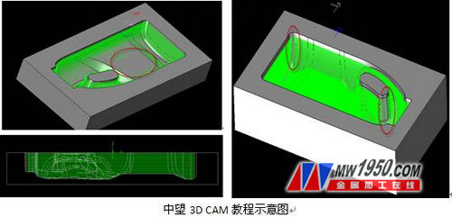
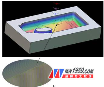
Engineers familiar with CAM machining know that using a contour cutter on a flat surface can lead to incomplete processing, as seen in the red area of the left image below. The tool path is uniform along the Z-axis, leaving certain areas unprocessed. On the other hand, switching to parallel milling might result in uneven material removal in sharp corners, as shown in the right image.
The angle-restricted finishing function in 3D software like Zhongwang 3D effectively addresses both issues. Here’s how you can achieve this efficiently:
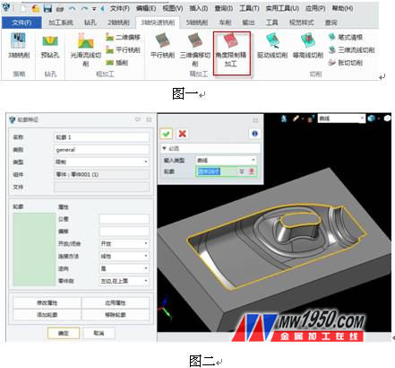
1. Click the “Process Operation†command in the menu bar (as shown in Figure 1), and insert the restriction contour and part into the feature (see Figure 2 below).
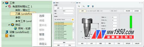
2. Choose the appropriate **tool** for the job.
3. Select the machining area based on the actual geometry of the part.
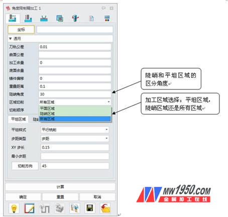
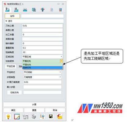
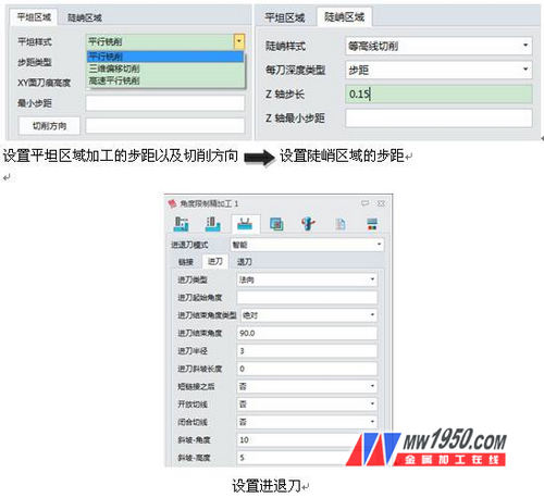
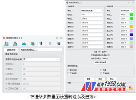
4. Set the required parameters for optimal results.
Once these steps are completed, the software calculates the full machining path, ensuring that both steep and flat regions are properly processed. The final result is a high-quality surface finish.
By following this workflow, design engineers can achieve precise results with Zhongwang 3D, reducing waste and improving overall CAM efficiency. Notably, Zhongwang 3D offers the latest hand-held tutorial training, making it easier for beginners to learn quickly and become proficient in 3D CAD/CAM technology. In addition, Zhongwang 3D 2013 includes a direct output to “3D Printer†(Print3D) function, enabling users to perform rapid prototyping and quality checks through 3D printing, which helps reduce production costs for enterprises.
**About Zhongwang 3D 3D CAD/CAM Software**
Zhongwang 3D is a preferred brand recommended by the State Ministry for military enterprises. It provides cost-effective 3D CAD/CAM solutions with features such as modeling, mold design, assembly, reverse engineering, sheet metal, and 2-5 axis machining. The software is fully compatible with other 3D CAD systems, comes with a rich library of parts, and is easy to learn and use. It also offers new learning tutorials and free downloads of 3D CAD drawings, helping users master 3D design and CAM programming faster. Download the latest version now and apply for free 3D CAD/CAM and 3D printing training.
Ductile Manhole Cover,Ductile Eletric Manhole Cover,Ductile Iron Eletric Manhole Cover, Electric Manhole Ductile Iron
Runchun Casting (Zhoushan) Co., Ltd. , https://www.en124casting.com