Foreword
In the design and testing of the unit pump common rail diesel engine ECU, it is essential to excite the camshaft (or crankshaft) speed signal. Instead of using an actual engine, a speed sensor can be replaced to generate and output the required frequency signal. However, the speed signal is not standardized—its phase, number of cylinders, and amplitude vary significantly, making it impossible to use off-the-shelf products. While dSPACE simulation can be useful for generating the camshaft speed signal, it requires a large instrument, a computer for display, and is both expensive and inconvenient to operate. Therefore, developing a compact, portable, and cost-effective diesel engine speed generator is highly necessary. The camshaft speed sensor typically outputs a square wave from a Hall effect sensor or a sine wave from a magnetic sensor. Regardless of the input type, the CPU’s front-end processing circuit can convert it into a square wave that the CPU can recognize. Hence, designing the system to output a versatile square wave signal is practical and efficient. The ECU is usually powered by 12V or 24V, so the power supply circuit is designed to accept 12–24V input. The C8051F310 microcontroller was selected due to its built-in timer, ADC, and sufficient I/O ports to meet system requirements. The speed signal is designed to be continuously adjustable, allowing simulation of various operating conditions such as starting, idling, and speed control. To support developers during testing, the device includes a character LCD module to display engine speed and toothed disc information. Since the amount of displayed data is limited, a cost-effective LCM1602 module was chosen. Additionally, the system stores different toothed disc structures in memory, enabling users to select the desired configuration and output the corresponding waveform, making the device suitable for various ECU software development tasks.Hardware Design
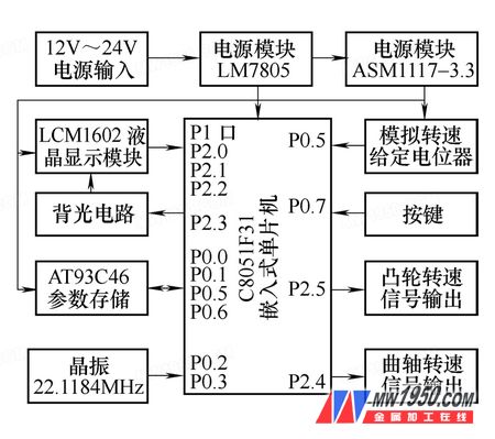
The hardware architecture of the camshaft speed simulation device is shown in Figure 1. It consists of a microcontroller system, a liquid crystal display (LCD) circuit, a speed reference circuit, a parameter storage circuit, and a power supply circuit. The C8051F310 serves as the central processing unit. It features an internal watchdog for power-on reset and program monitoring. The device is powered by a 12–24V DC supply and uses two-stage voltage regulation to produce 5V and 3.3V power supplies. An IO port expansion button on the CPU allows selection of the gear plate structure serial number, which is stored in E2PROM. The speed reference potentiometer’s output is sampled by the CPU’s onboard ADC and converted into a digital signal proportional to the speed. Two IO ports are used to adjust the output frequency of the camshaft square wave signal. The LCM1602 character LCD module is used to display the rotation speed and the toothed disc structure, operating in an 8-bit bus mode. The housing is made from a standard plastic case with minor modifications.
Figure 1: System Hardware Structure Diagram
In-Wall Shower Set,Brass In-Wall Shower Set,Contemporary Brass Shower Set,High End Brass In-Wall Shower Set
Kaiping Rainparty Sanitary Ware Technology Co.,Ltd. , https://www.rpshower.com