With the development of science and technology and computer software and hardware, 3D CAD software has been widely used in the machinery industry. Xigong Group's tooling design department is also beginning to use 3D CAD software UG NX3 for tooling design. But no matter what kind of software is used for design, according to our current production mode, we will always provide a complete engineering drawing for the tooling manufacturing and use workshop.
Many people just started to use 3D software for tooling design. Because the engineering part of 3D software is inconvenient to operate, it is always designed with 3D software. After the 2D projection image is generated, the design result can be converted into 2D software. The format is post-processed for the drawing. Obviously, when a 2D projection is converted to a file in another format, the association between the 3D model and the 2D drawing is broken. If the 3D model is changed, the 2D drawing can only be re-exported and processed or manually modified, which is not desirable in terms of improving design efficiency or improving design quality.
UG software is a general-purpose software. The two-dimensional drawing environment, symbols, frames, title bars, and schedules in the platform do not meet our corporate standards and cannot be directly applied. Therefore, when we use UG software for tooling design, Developed 2D engineering drawing templates that meet national and corporate standards.
2. Design of UG drawing template
2.1 Two-dimensional plotting environment and frame settings
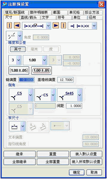
Using UG's "drafting" module, design A0, A1, A2, A3 and A4 five sizes of frames, and pre-define various parameters in each frame, such as size text size, arrow type and size, various Labeling method, etc. (Figure 1), so that when using the template, there is no need to waste time to adjust, which greatly improves the efficiency of the two-dimensional map.

figure 1
2.2 Autofill of the title bar
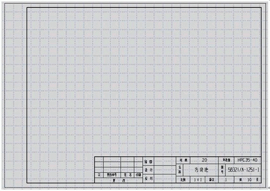
In each frame, set the company's special tooling assembly drawing and part drawing title bar, fill in the name, drawing number, material and other items in the corresponding position, as shown in Figure 2.

figure 2
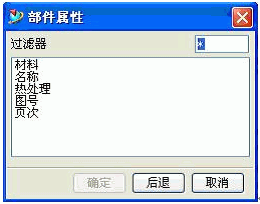
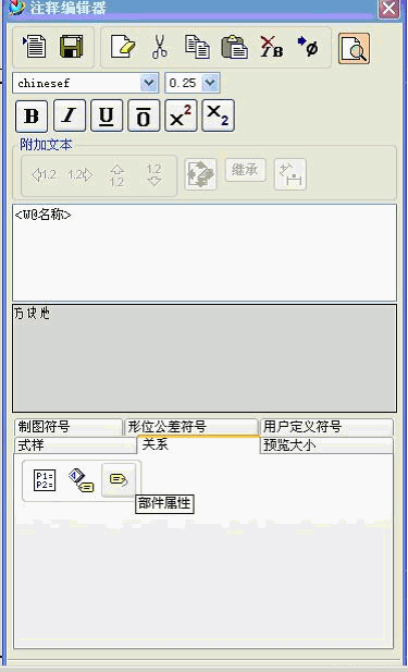
Use the "Relationship" command in the UG Draftng "Comment Editor" command to associate items such as name, drawing number, material, etc. with the properties of the part itself (Figures 3 and 4), so that during tooling design, just give Zero, the component is given the attribute, and the corresponding attribute can be automatically filled in the title bar when the drawing is taken out.

image 3

Figure 4
Next page
Cold Drawn Steel Tube,St52 St37 Steel Tubes,Mild Steel Pipes
Province Gold Mysterious Pipe Co., Ltd. , http://www.hbseamlesspipe.com