As the only CAD/CAM integrated 3D CAD software in China, Zhongwang 3D can provide customers with complete solutions from design to processing. Not only that, but its unique "learning by side" system greatly reduces the learning threshold of software, which is not available in other 3D CAD software. With the increasing application of Zhongwang 3D in various industries, how to insert the geometric tolerance in Zhongwang 3D has become a concern of many designers. Today I will introduce to you how to insert geometric tolerances in Zhongwang 3D.
First, let us introduce the definition of geometric tolerance.
Geometrical tolerance: not only the dimensional error of the processed parts, but also the actual shape or mutual position of the points, lines and faces constituting the geometric features of the parts, and the shape and mutual position specified by the ideal geometry are inevitably different. The difference is the shape error, and the difference in mutual position is the position error, collectively referred to as the tolerance of form and position. Includes shape tolerances and position tolerances.
Any part is made up of points, lines, and faces. These points, lines, and faces are called features. There are always errors in the actual elements of the machined part relative to the ideal element, including shape and position errors. Such errors affect the function of the mechanical product and should be specified in the design and marked on the drawing in accordance with the specified standard symbols.
Shape tolerance refers to the total amount of variation allowed by the shape of a single actual element.
Shape tolerances are expressed in shape tolerance bands. The shape tolerance band includes four elements of the tolerance band shape, direction, position and size. Shape tolerance items include: straightness, flatness, roundness, cylindricity, line profile, and face profile.
Position tolerance is the total amount of change allowed for the reference to the position of the actual feature.
After opening the 3D in the middle, create a part. At this time, draw the required parts or weldments according to your needs. After the drawing is finished, click the right mouse button and the option shown in Figure 1 appears. Select “2D Drawing†to enter the drawing environment of the 3D drawing. Draw a two-dimensional map of the current part based on the view you need. In this environment, let's talk about the insertion of geometric tolerances.

The insertion method of the geometric tolerance is: in the drop-down menu under the 3D drawing environment, find the "label" under the "Insert" menu bar, and then find the "Tolerance Set" under this "Label", inside, Contains four options: geometric tolerance symbol, reference symbol, reference point symbol, and reference target area symbol. As shown in Figure 2.
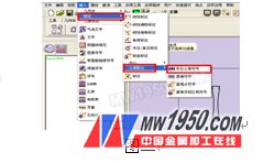
(Or under the 'Label' function tab, find the 'shape tolerance' icon  , click it to enter the geometric tolerance function).
Bar Fence,Bar Barrier,Palisade Fencing
Xinlong Wire Mesh Manufacture Co., Ltd. , http://www.hebwiremesh.com