1 Scope
This standard stipulates the test of the ability of the photovoltaic module to withstand ultraviolet irradiation when it is exposed to ultraviolet radiation. This test is suitable for evaluating the resistance to ultraviolet radiation of materials such as polymers and protective layers.
The purpose of this test is to evaluate the ability of the module to withstand exposure to ultraviolet radiation at wavelengths between 280 and 400 nm. Before carrying out this test, light aging or other pretreatment should be carried out according to GB/T 9535 or GB/T 18911.
2 normative references
The clauses in the following documents have been adopted as references to this standard. For dated references, all subsequent amendments (not including errata content) or revisions do not apply to this standard, however, encourage the parties to reach an agreement based on this standard to study whether the latest version of these documents can be used . For undated references, the latest version is applicable to this standard.
GB/T 6495.1-1996 Photovoltaic devices - Part 1: Photovoltaic current-voltage characteristics measurement (idt IEC 60904-1:1987)
GB/T 6495.3-1996 Photovoltaic devices - Part 3: Principles of measurement of photovoltaics for the surface and spectral irradiance data (idt IEC 60904-3:1989)
GB/T 9535-1998 Design and identification of crystalline silicon photovoltaic modules for ground use (idt IEC 61215; 1993)
GB/T 18911-2002 Design and identification of thin-film photovoltaic modules for use on the ground (IEC 61646:1996, idt)
3 Initial measurement
The following initial measurements should be made:
- Visual inspection according to GB/T 9535-1998 or GB/T 18911-2002;
- Measurement of IV characteristics under standard test conditions according to GB/T 6495.1-1996;
- Insulation tests according to GB/T 9535-1998 or GB/T 18911-2002.
4 equipment
The equipment consists of the following:
a) A temperature controlled test chamber with a window or a device that can hold a UV light source and assembly. The test chamber must maintain a dry environment with a module temperature of 60 °C ± 5 °C.
b) A UV source with the required total irradiance can be provided on the test surface of the module with a uniformity of ±15% of the radiation and a different spectral region specified in 5c). The final test report should specify the type of UV light source used.
C) The device for testing and recording the temperature of the module shall ensure that the accuracy is ±2°C. The temperature sensor shall be glued in the middle near the back or front of the module. If several components are tested simultaneously, monitor the temperature of a representative component.
d) A calibrated radiometer capable of measuring the irradiance generated by the ultraviolet light source on the test surface of the module.
See Appendix A for recommended UV light sources.
5 steps
The test should be based on the following steps
a) Use a calibrated radiometer to measure the irradiance of the component test plane and ensure that the wavelength is between 280nm and 400nm. The irradiance of the test spectrum does not exceed 5 times its corresponding standard spectral irradiance. Standard AMI.5 Sun The irradiation distribution is given in Table 1 of GB/T 6495.3. Spectral irradiation with a guaranteed wavelength below 280 nm is not measurable and the uniformity of illumination at the test plane is ±15%.
b) Mount the assembly on the test plane. According to a) Select the area so that the UV radiation is perpendicular to the front of the assembly.
C) To maintain the module temperature within the specified range, the minimum exposure to the module is:
- Wavelength range 280nm~320nm, 7.5kWh, m-2 and
- The wavelength range is 320nm ~ 400nm, 15kWh · m-2.
d) Adjust the assembly so that the UV radiation is perpendicular to the back of the module.
e) Repeat step C) with an exposure of 1000 for the positive irradiation level.
Note: Under revision IEC 61215, the UV irradiation test of monocrystalline silicon modules is not performed in steps d) and e), and step c) is changed to: “The irradiation dose received by the module is: Wavelength range 280nm~385nm, 15kWh· M2." When using this standard, single crystal silicon components can be referred to.
6 final test
Repeat the following measurements:
- Visual inspection according to GB/T 9535-1998 or GB/T 18911;
- measuring IN characteristics according to GB/T 6495.1-1996 under standard test conditions;
- Insulation test according to GB/T 9535-1998 or GB/T 18911.
7 Requirements
The tested components should meet the following requirements:
- No serious appearance defects as specified in GB/T 9535-1998 or GB/T 18911.
- Under the standard test conditions, the maximum output power decline is not greater than 500 pre-test values. For thin-film modules, the maximum output power under standard test conditions should be greater than the minimum value of the nominal power of the component provided by the manufacturer.
- According to the provisions of GB/T 9535-1998 or GB/T 18911, the insulation resistance should meet the requirements of the initial measurement.
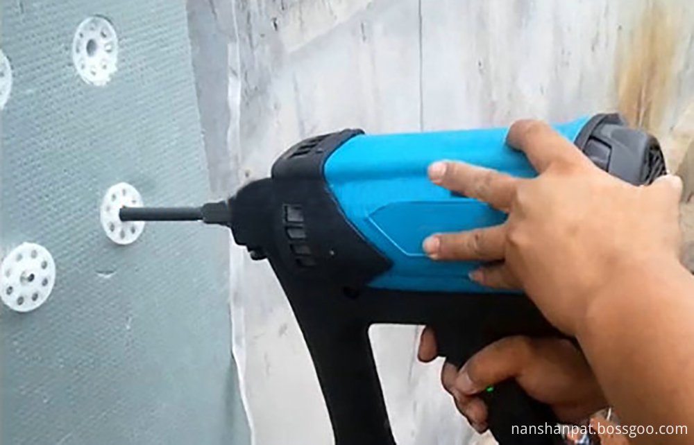
NANSHAN Insulation Fasteners are specifically fabricated to meet the exacting requirements of toughness and durability that enable them to penetrate dense concrete and structural quality steel.
We maintain only the highest standards in the materials, production techniques and quality control measures used to manufacture our fasteners, assuring consistent, optimum quality in every fastener.
NANSHAN Drive Pins can be used for the Powder Actuated Tools and gas actuated tools of
NANSHAN®, POWERS®, RAMSET®, HILTI®, SIMPSON® and BLUE POINT FASTENERS®.

Insulation Fasteners
Insulation Fasteners,Insulation Anchors,Insulation Nails,Insulation Board Nails
Sichuan Nanshan Powder Actuated Fastening System Co., Ltd. , https://www.nanshanpat.com